Tempest Programmable TV Game Composite Mod
A simple circuit to get composite video alongside audio out of a Tempest Programmable TV Game console using a BC557 transistor. The circuit is based off of the schematic from John’s Retro Workshop schematic.
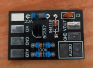
In my earlier post on repairing the console I created a test circuit first before ordering a circuit board from JLCPCB. The circuit boards arrived and I went ahead and populated the board.
The two 100k ohm resistors at the bottom for the audio output are optional as the console itself has a speaker built in. You can have the audio going to the built in speaker and TV at the same time or if that is annoying you can mute the built in speaker.
The parts used are:
- BC557 transistor
- 1N4148 diode
- 330 ohm resistor
- 2x100k ohm resistors (optional for the audio)
- 4.7nF ceramic capacitor (you might need to play with different values)
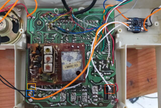
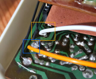
The solder points can be found in the following locations:
- Red box is the audio solder point (AUD)
- Orange box is the video solder point (VID)
- Blue box is the ground solder point (GND)
If you want to get your own circuit boards printed, you can download the gerber file from my GitHub.


